Categories
How To Order
Contact us for information
Email or speak to a Product AdvisorView styles and features
Select options and request quoteOrder online or by phone
Call 203-801-5900
or 800-341-1620
Optical Speed Gate - Clear Flap Panels


Product Description
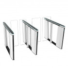
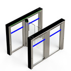
The Optical Speed Gate - Clear Flap Panels is a slim, transparent access-control solution for secure interior entrances. It is suited to offices, government and financial facilities, retail environments, telecommunications sites, educational buildings, and similar locations.
Motorized glass flaps control passage in one or both directions. In Normally Closed mode, they open only after authorization; in Normally Open mode, they remain open unless unauthorized entry is detected.
Detection and User Guidance
Optical sensors identify tailgating, piggybacking, intrusion, wrong-way travel, and lane timeouts. Unauthorized use can activate an integrated alarm.
LED pictograms communicate lane status: green arrows authorize travel, red symbols indicate a closed lane, and flashing indicators signal alarm, emergency, or technical conditions.
Glass Barrier Heights
The system is available with several glass barrier heights:
- 35 inches — approximately 880 mm
- 47 inches — approximately 1,200 mm
- 59 inches — approximately 1,500 mm
- 71 inches — approximately 1,800 mm
These barrier heights can be specified with the available cabinet lengths.
Tall Panels: Optical Speed Gate - Clear Flap - Tall Panels
This makes the system particularly flexible when an architect needs to balance visual openness, pedestrian separation and security requirements.
Standard and Wide Passage Options
Passage options include a 24-inch standard lane and a 35-inch wide lane for wheelchairs and larger items. Combination cabinets can create one standard and one wide lane in the same array.
Cabinet lengths are 47, 55, or 74 inches (1,200, 1,400, or 1,870 mm). End, center, and combination cabinets support multi-lane layouts. Cabinet width is approximately 5 inches (120 mm), excluding rotor-column clearance.
Multiple cabinets can be combined to create additional lanes. A complete lane uses left- and right-side cabinets, while center and combination cabinets can be used to create multi-lane installations.
Materials and Operation
The chassis, plinth, end-leg posts, and rotor column are stainless steel with a 10 mm glass inlay. The flaps use 10 mm tempered glass. Black technopolymer is standard for the lid, with additional architectural finishes available.
A DC motor and gearbox drive each flap. A rotary encoder and microprocessor controller regulate panel position, speed, and travel limits.
Safety and Emergency Egress
Safety photocells and force sensors stop panel movement when an obstruction is detected. A lower safety-sensor kit is optional.
The unit includes manual push-opening, anti-panic push-opening, and emergency-egress capability. A voltage-free fire-alarm input provides the required emergency response; confirm project-specific behavior in the product documentation.
Access Control Integration
Digital I/O, RS232, and RS485 communications support connection to access-control, card-reader, and remote-control systems.
Installation, Drilling, Trenching and Conduit
Coordinate equipment locations, power, access-control connections, and conduit routes before the finished floor is completed. The finished floor must be level within ±5 mm.
Minimum foundation requirements are:
- 47.2-inch cabinet: 1,300 × 400 × 150 mm
- 55.1-inch cabinet: 1,500 × 400 × 150 mm
- 73.6-inch cabinet: 2,000 × 400 × 150 mm
Use concrete with a minimum Fck cube strength of 30 N/mm² and provide at least 70 mm of bolting depth. Route conduits at least 140 mm below finished-floor level, with a rise of at least 50 mm from the foundation.
For retrofit work, check drilling and trenching locations for utilities, reinforcing steel, and other concealed conditions. Use an approved baseplate or floor-saver arrangement when the selected installation requires one.
Specifications
- Product Type: Optical flap speed gate
- Panel Heights: 34.6", 47.2", 59.1" and 70.9"
- Passage Widths: 23.6" standard / 35.4" wide
- Cabinet Lengths: 47.2", 55.1" and 73.6"
- Construction: 304 stainless steel with 10 mm glass
- Operation: Motorized, bi-directional glass barriers
- Security: Tailgating, piggybacking, intrusion and wrong-way detection
- Access Control: Card, proximity and compatible systems
- Power: 230 VAC, 50 Hz
- Installation: Floor-mounted; concrete foundation and below-floor conduit required
- Foundation: Minimum 150 mm (5.9") depth and 400 mm (15.7") width
- Conduit: Minimum 140 mm below finished floor with 50 mm minimum stub-up
Product Features
Description:
Panels: 35",47", 59", or 71"
Description1:
Passage Width: 24" or 35"
Description2:
Length: 47", 55", or 74"
Description3:
Baseplate Options
Description4:
Bi-Directional Operation
S:
Access Control Ready

0
(hours)
:
0
(minutes)
:
0
(seconds)